Free Download Cadence SPB Allegro and OrCAD 17 for Windows, it includes various programs to design schematic, simulation and analysis of electronic circuits. Need for speed underground iso downloadwesternhunter. This is the best and most professional software simulation and analysis electronic circuits and electronic design automation. Orcad Schematic Viewer, free orcad schematic viewer software downloads.
Article Technical Rating: 7 out of 10 There are numerous software packages available for designing printed circuit boards (PCBs), too many in fact. That being said, there are three PCB design packages that tend to be the most popular and considered the best: Altium Designer, Eagle, and OrCad. However, for hardware entrepreneurs, startups and makers I prefer a less well-known PCB design. OrCAD / Allegro Free Physical Viewer The Cadence® OrCAD® /Allegro® FREE Physical Viewer is a free download that allows you to view and plot databases from OrCAD PCB Editor, Allegro.
Orcad Viewer Free Download Windows 10

Orcad 9.2 Download
The first step to obtain one of theseprinted circuit boards(PCBs) is to design it using one of the specific tools on the market. One of the most popular ones is OrCAD.
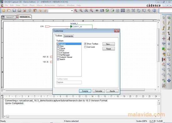
OrCAD is the most powerful and intuitive tool to design printed circuit boards. The demo version offers you the possibility to evaluate the following functions: OrCADCapture, OrCADCapture CIS Option, PSpice A/D, PSpice A/A, OrCADPCB Editor and SPECCTRA.
The basic steps that have to be taken to designa printed circuit board with OrCAD are:
1. Design the circuit by creating the schematic in the 'Capture' module.
2. Generate the circuit's netlist.
3. Import the netlist to 'LayoutPlus'.
4. Place the components and trace the pathways.
5. Generate the files of its design.
Once the design of the copper pathways on the board has been finished, and we have simulated the behavior of the design, the next step will be to design the PCB from an insulating material, like for example a photosensitive fiberglass board.
